Embed Schedule
- General Overview
- Tips and Tricks
- Related Tools
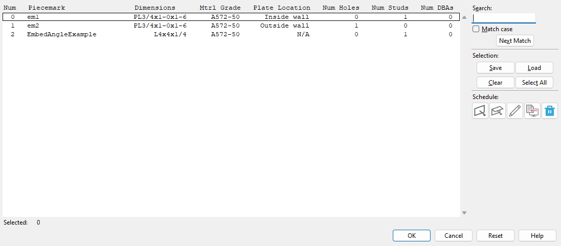
Embed Schedule Options
Piecemark : The standard submaterial mark that you want to assign to all copies of this particular plate when added to column members.
Note: The piecemark entered here must be unique. If the piecemark entered is already assigned to another material, an alert opens when you click OK, telling you that the entry must be a unique piecemark.
Dimensions : For an embed plate, this is the thickness, width, and length of the plate; for a continuous embed, this is the section size of the angle or channel material from the local shape file.
Mtrl Grade : A36 or A572-50 or etc.
For an embed plate, this is the Steel grade of the rectangular plate material.
For a channel or angle embed, this is the Steel grade of the rolled section material.
Setup: All steel grades populating this list box (
), come from Home > Project Settings > Job > Material Grades > Plate Grades or Channel Grades or Angle Grades.
Plate Location : Inside wall or Outside wall .
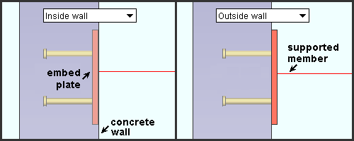
Inside wall embeds the plate material in the concrete wall.
Outside wall locates the plate flush to the concrete wall.
Num Holes : The number of Hole patterns applied to the embed plate or continuous embed.
Num Studs :The number of Stud patterns applied to the embed plate or continuous embed.
Num DBAs : The number of DBA patterns applied to the embed plate or continuous embed.
Embed Schedule
 Add Embed Plate : Opens a window to add a new embed plate. (This link takes you to the Embed Plate Edit window with the same settings)
 Add Continuous Embed : Opens a window to add a new continuous embed. (This link takes you to the Embed Edit window with the same settings)
 Edit Selected Line(s) : Opens the edit window for the one or more lines that you selected. Double-clicking a line also opens the entry window.
 Copy Selected Line(s) : Adds an exact duplicate of the selected line(s). Everything except the piecemark and the line number will be the same.
 Delete Selected Line(s) : removes the selected line(s).
Selection
Search : The Search widget searches the schedule for similar text and selects the closest match. Match case performs a case-sensitive search. Next Match cycles to the next line that closely matches the search criteria.
Save : The Save button allows you to save the selected embeds into a selection list. You will be prompted for a selection file name and location on your computer.
Load : The Load button allows you to load a previously saved selection list of embeds. A browse window opens to search for a previously saved file.
Clear : Deselects all embeds that are currently selected.
Select All : Selects all embeds in the schedule.
OK (or the Enter key) closes this window and applies the settings.
Cancel (or the Esc key) closes this window without saving any changes.
Reset undoes all changes made to this window since you first opened it. The screen remains open.
- You can edit individual embeds in the model. They are independent members, different from the beams or joists on whose windows an Embed schedule entry was made. The edit windows for embed members are Embed Plate Edit (plates) and Embed Edit (channels and angles).
- Editing an embed in the model does not affect the Embed Schedule .
- Within the
 Connection specifications for beams, you'll find options for Embed plate location (clip angle) or Embed plate location (shear plate) or Embed plate location (beam seat).
-
 Red-colored highlighting identifies an entry that is invalid. Unless you change that entry, you will not be able to close the entry window using OK.
Hover your mouse cursor over the icon to make a tooltip appear with more information.
Red-colored highlighting identifies an entry that is invalid. Unless you change that entry, you will not be able to close the entry window using OK.
Hover your mouse cursor over the icon to make a tooltip appear with more information.
- Embed schedule entry ( Embed Plate Edit )
- Embed schedule entry ( Embed Edit )
- Embed schedule entry ( Auto Standard Connections )
- Embed schedule entry ( Beam Edit )
- Schedule entry, top chord ( Joist Edit )
- Schedule entry, bottom chord ( Joist Edit )
- Embed schedule entry ( User Defined Connections )
- Concrete wall
- Joist to concrete connection guide

